Since I already wrote about presentation sheets in my last blog post I will only write about families and color schemes in this post.
Families
 |
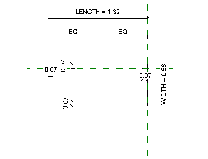
| Figure 1 - reference planes |
The planes of reference are those that delimit us the drawing and help us to place the different elements of the family. The two planes that define origin form the point of insertion of the family. It is important that the planes of origin be anchored so that they do not move.
Reference planes can be dimensioned and parameterized to control the distances between them. The dimensions create parameters to previously decide the distances of the objects linked to the planes.
 |
| Figure 2 - parameter |
When designing a family the start point is to create reference planes. These reference planes helps us placing the elements we are going to draw. The intersection of two planes will create an origin where you can easily anchor an element.
What is great about Revit you can control the distances of the objects linked to the planes. They can be dimensioned and parameterized.
In the elevation you are able to put parameters to define the heights of the objects.
The way of drawing an object is to draw shapes on two sides of a box, and the union of the creates a figure. You can use the command extrusion to extrude one shape. When you are showing it in the 3D view you can easily anchor an extrusion with the height parameters.
 |
| Figure 3 - elevation |
The bench
In our case we designed a simple bench. All we needed to do was to extrude the rectangle for the seat and put legs. The legs can be placed with doing an extrusion and kept in place with help of parameters. We have to get them to have the same distance even if the size of the axes are being increased. For this we will create a parameter linked to the axes and adding the distance we want for the separation.
(pictures are borrowed from Francisco and Margaritas delivery, because of problems with opening my file)
 |
| Figure 4 - bench with parameter |
 |
| Figure 5 - bench with parameter |
 |
| Figure 6 - bench with parameter |
Inserting one family into another is called nested families.
When using a polar matrix you can create a parameter to manually decide how many items are placed, for example chairs on a table.
The parameters can also define material, text, volume, area etc.
The limit is endless of what you can design.
Color schemes
When creating a color scheme we are creating rooms obtained by an enclosed surface. If a room is not limited to its boundaries you will need to create a room separation line. When the rooms are created we will create a color scheme to define aspects such as the volume, room name etc. When the rooms are created the program automatically prepares the for you in the legend color scheme.
In the planning tables you can select information such as the room name, volume, areal, floor level etc. Revit prepares and calculates the information for you. You can select what you want to be shown in the planning tables.
 |
| Figure 7 - color scheme |
 |
| Figure 8 - planning table |
 |
| Figure 9 - planning table |
 |
| Figure 10 - color scheme |
 |
| Figure 11 - color scheme properties |
Presentation
In the viewports you can select what information you want to be shown such as the floor plan
name and the scale.
We had issues printing the book where the buttons of the print properties were not responding. I believe it is a problem of my computer and am trying to solve it.
(We are aware that some things are missing such as the back of the bench and some final adjustments on the final delivery. With several submissions and my exam in mathematics this week I simply have not have time for everything. Though I am ready to give full effort to do a good final submission for next delivery!)


Comments
Post a Comment